Flexible Busbar Bend Radius: Design Considerations for Tight Spaces
When installing flexible busbars in confined electrical enclosures or battery modules, the minimum bend radius is typically 1.5–2 times the busbar thickness for standard copper laminates and 3–5 times the thickness for high-voltage or multiple-layer stacks. Exceeding these limits risks laminate cracking, insulation damage, or conductor fatigue. The exact radius depends on laminate construction, copper layer count, and operating temperature. Always consult manufacturer specifications for your specific busbar design.
Application Scenario
Flexible busbars are essential in modern power distribution systems where space is at a premium. Common applications include:
- Battery energy storage systems (BESS) – connecting battery cells and modules within tight enclosures [K1]
- Switchgear and control cabinets – routing power between components in crowded panels
- Renewable energy inverters – managing AC/DC connections in compact housings
- Electric vehicle battery packs – accommodating vibration and thermal expansion in limited spaces [K1]
In these environments, engineers must balance electrical performance with mechanical constraints. A busbar that cannot achieve its required bend radius may force a larger enclosure or compromise current-carrying capacity.
Engineering Decision Criteria
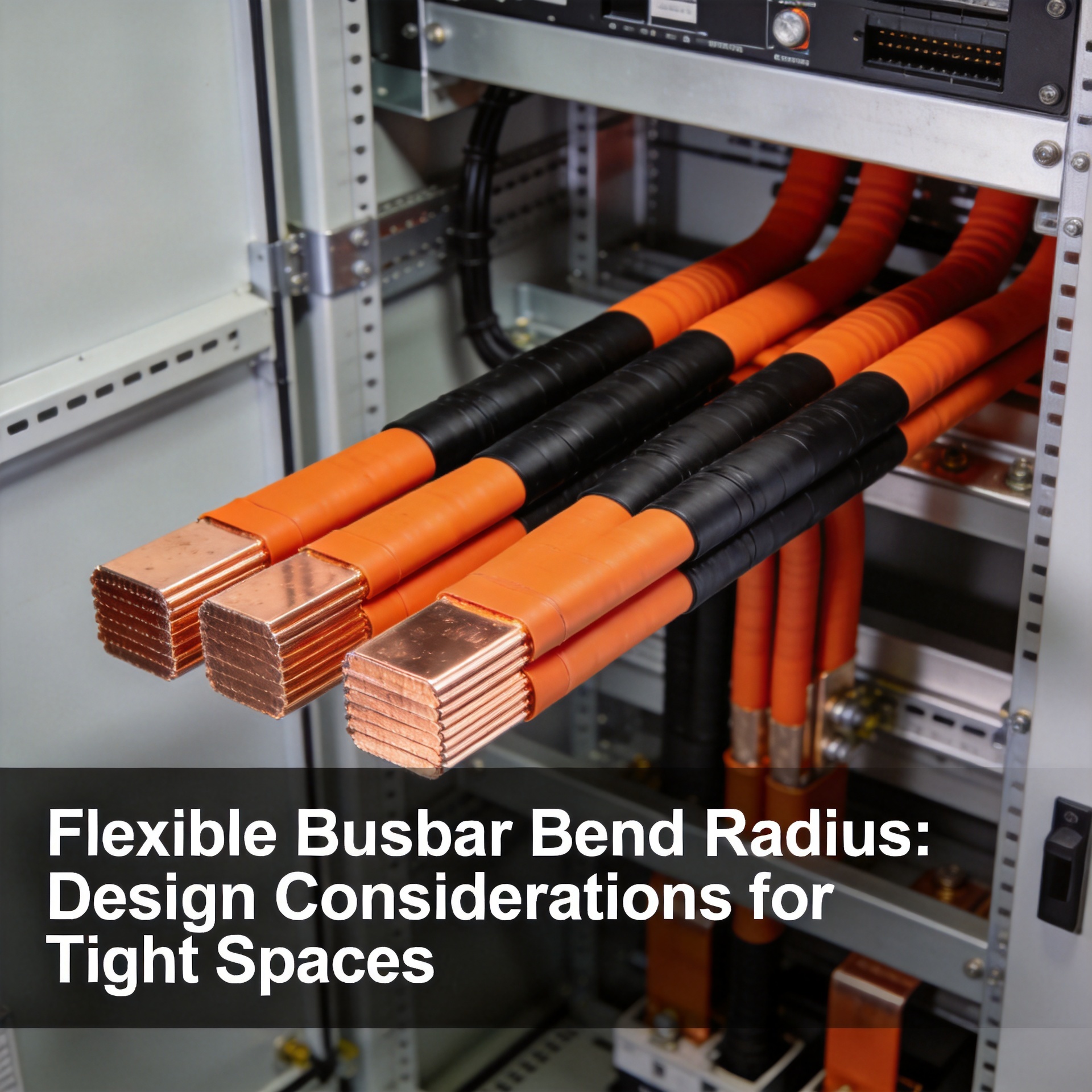
Key factors determining minimum bend radius
| Factor | Impact on Bend Radius | Notes |
|---|---|---|
| Copper layer thickness | Thicker layers require larger radii | 0.1mm foil vs 0.3mm layers differ significantly |
| Number of layers (stack) | More layers increase stiffness | 3-layer stack may need 50% larger radius than single-layer [K2] |
| Insulation type | Thicker insulation reduces flexibility | Polyimide vs PET insulation have different bend limits |
| Operating temperature | Higher temperature may soften laminates | Consult derating curves above 105°C |
| Bend axis orientation | Bending across vs along layers | Always bend perpendicular to layer plane |
Recommended design equation
For most flexible busbar laminates:
R_min = t × k
Where:
- R_min = minimum bend radius (mm)
- t = total laminate thickness (mm)
- k = material factor (typically 1.5–2.0 for standard copper laminates; 3.0–5.0 for multi-layer or high-voltage designs)
Example: A 0.5mm thick single-layer flexible busbar with k=2 → R_min = 1.0mm
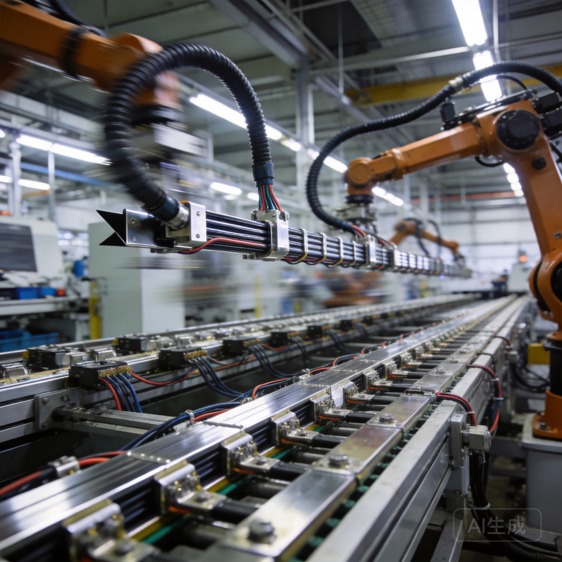
Suitable vs. Not Suitable Cases
Suitable for tight spaces when:
- The busbar has fewer than 5 copper layers [K2]
- Total laminate thickness is under 1.0mm
- Bend angle is ≤ 90° and bend forms a smooth curve (no sharp creases)
- Operating temperature remains below 125°C
- The bend is in the same plane as the busbar’s flat face
Not suitable when:
- Multiple sharp 180° bends are required in a short span
- The busbar exceeds 3mm total thickness and requires a radius under 5mm
- The application involves continuous flexing (use braided busbars instead)
- The bend radius conflicts with clearance requirements to grounded metal parts
- Insulation creepage and clearance distances cannot be maintained after bending [K3]
Procurement Notes
-
Request bend radius specifications: Ask your supplier for the exact minimum bend radius for your chosen laminate structure. Do not rely on generic values.
-
Prototype first: Always test bends on sample pieces before full production, especially for multi-layer or thick laminates.
-
Consider tool radius: When using bending dies, the tool radius should match or exceed the minimum bend radius to prevent stress concentration.
-
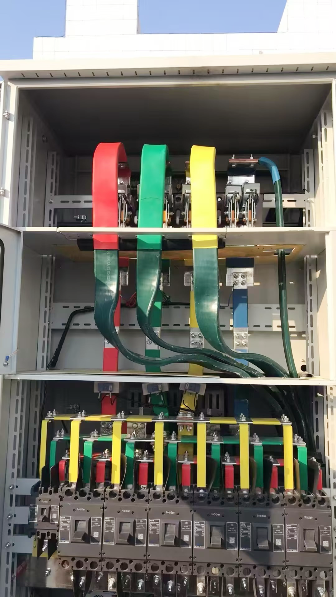
Inspect after bending: Look for visible cracks, delamination, or insulation wrinkling. Any defects indicate an excessive bend.
-
Allow tolerance: Design with 20–30% margin above the stated minimum bend radius to account for manufacturing variability and thermal effects.
Frequently Asked Questions
Q: Can I bend a flexible busbar to a 0mm radius (fold it like paper)? A: No. Flexible busbars have a minimum bend radius that depends on their laminate construction. Folding to a 0mm radius will cause copper layer cracking and insulation failure. Always maintain the manufacturer’s recommended minimum radius.
Q: How does operating temperature affect the bend radius? A: Higher temperatures can soften the insulation and copper layers, potentially reducing the safe minimum bend radius. However, prolonged high-temperature operation may also degrade the laminate bond. Consult the supplier for temperature derating curves above 105°C.
Q: What happens if I use a bend radius that is too small? A: Using too small a bend radius can cause delamination, copper cracking, insulation damage, and reduced current-carrying capacity. In severe cases, this leads to electrical failure, short circuits, or fire risk.
Q: Is there a difference between bending along the length vs. across the width? A: Yes. Flexible busbars are designed to bend in the plane perpendicular to the laminate layers. Bending along the layers (edgewise) is typically not recommended and may require different design rules.
Q: Do multiple layers affect the bend radius requirement? A: Yes. Multi-layer flexible busbars are stiffer, so they require a larger bend radius. A 3-layer stack may need 50% or more bend radius compared to a single-layer busbar of the same total thickness.
About the Author Yanghua Engineering Team — 15+ years of flexible busbar design, manufacturing, and project delivery for energy storage, solar PV, EV charging, and industrial electrification.
The team holds a VDE flexible industrial cable training certificate (2024) and operates an in-house R&D Experimental Center. Yanghua flexible busbar products have passed type testing with official test reports.
Contact: info@yhflexiblebusbar.com | Hotline: 400-883-1383