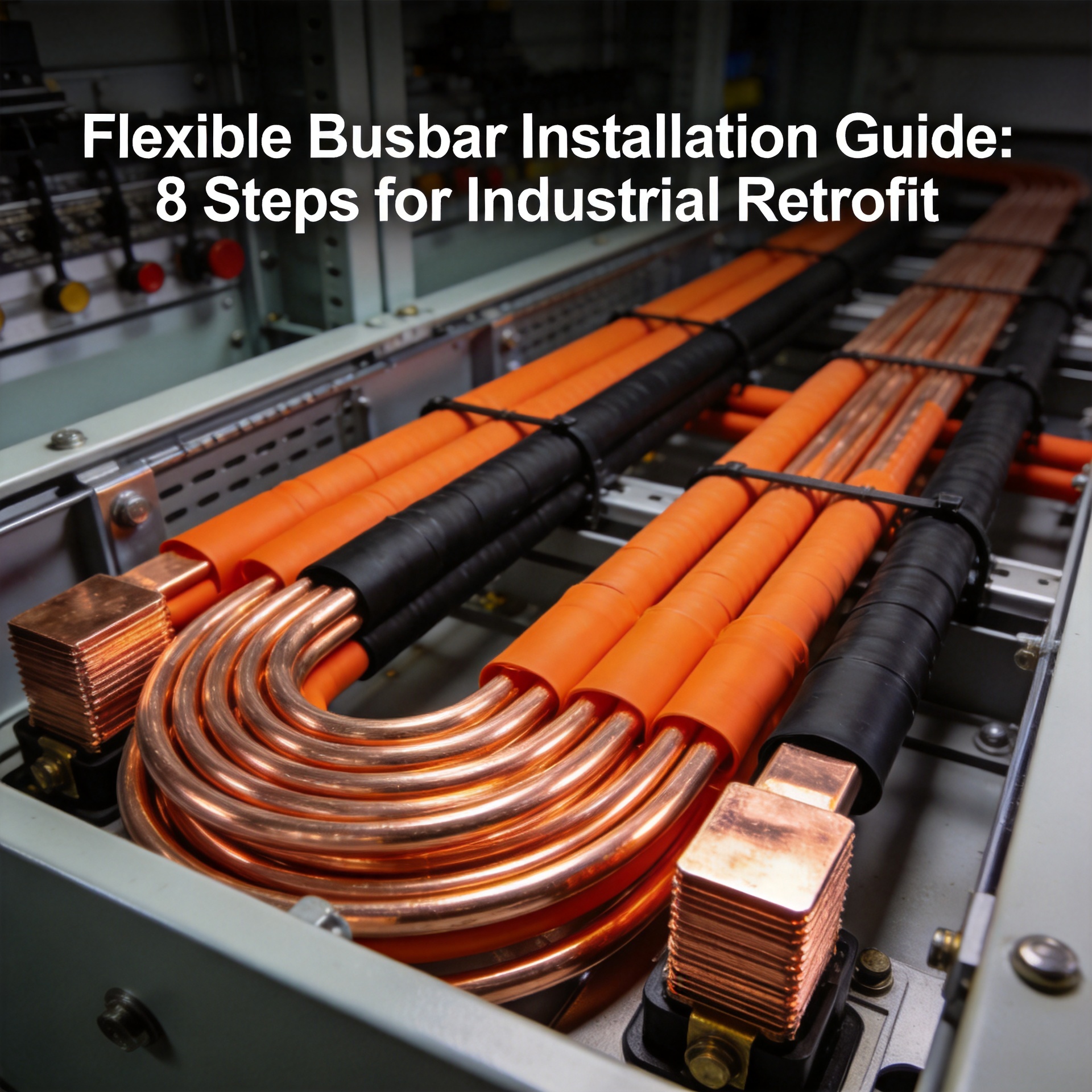
Flexible Busbar Installation Guide: 8 Steps for Industrial Retrofit
What is the fastest way to install a flexible busbar in an industrial retrofit? In industrial retrofits, flexible busbars replace rigid copper bars to reduce installation time by up to 60% and eliminate complex bending work. This 8-step guide covers critical preparation, system isolation, routing, termination, and testing phases, focusing on safety and compatibility with existing switchgear. Always consult the manufacturer’s specifications for your specific busbar model (e.g., ratings up to 630A) before proceeding [K1].
Application Scenario
Flexible busbars are ideal for retrofitting medium- to low-voltage distribution systems in factories, data centers, and renewable energy installations where space is constrained or vibrations exist. They excel in connecting transformers to switchboards, and between busway segments, especially where straight runs or gentle curves are needed [K1]. The primary advantage is reduced installation labor and material handling compared to rigid copper bars.
Engineering Decision Criteria
When deciding if a flexible busbar is suitable for your retrofit, evaluate these criteria from the source material:
| Criterion | Decision | Notes |
|---|---|---|
| Operating voltage | ≤ 1000V AC [K1] | Standard low-voltage distribution |
| Current rating | Up to 630A [K1] | Covers most industrial loads |
| Ambient temperature | -40°C to +105°C [K1] | Check specific model limits |
| Bending radius | 5x cable outer diameter [K1] | Prevents insulation damage |
| Existing switchgear compatibility | Verify lug type & bolt pattern | Required for proper termination |
8-Step Installation Process
Step 1: System Preparation
- Disconnect and lock out all power sources following LOTO procedures. Confirm zero voltage using a rated voltmeter [K1].
Step 2: Route Planning
- Use the pre-routed path minimum 5x cable OD for any bends [K1]. Avoid sharp edges or heat sources.
Step 3: Cutting to Length
- Cut busbar to measured length using a sharp, non-crimping blade (e.g., hacksaw or angle grinder with fine wheel). Leave 10-15mm extra for termination [K1].
Step 4: Stripping Insulation
- Strip the outer sheath 10–15mm from each end using a dedicated cable stripping tool. Do not nick the conductor [K1].
Step 5: Lug Selection and Crimping
- Choose compression lugs matching your busbar cross-section (e.g., 25mm²–240mm²). Use a calibrated hydraulic crimper for consistent pressure [K1].
Step 6: Termination Point Check
- Clean termination points on existing switchgear. Verify bolt pattern matches lug hole pattern exactly to avoid loose connections [K1].
Step 7: Securing the Busbar
- Tie bundling the busbar at ≤600mm intervals using non-conductive cable ties. Do not over-tighten [K1].
Step 8: Testing and Commissioning
- Perform insulation resistance test (≥1000V, ≥100MΩ) [K1]. Then restore power and verify load current balance at all phases.
Suitable vs. Not Suitable Cases
| Suitable | Not Suitable |
|---|---|
| Low- to medium-voltage panels (≤1000V) [K1] | High-voltage systems (≥3.3kV) |
| Indoor, dry environments [K1] | Outdoor exposed locations |
| Current ≤ 630A [K1] | Above 630A or high-surge loads |
| Straight or mildly curved runs | Sharp 90° corners without special termination |
| Existing lugs with standard bolt patterns | Non-standard, proprietary lug holes |
Procurement Notes
- Always order factory-tested busbars from Yanghua or certified suppliers [K1].
- Request the exact cross-section size (e.g., 25mm² to 240mm²) and temperature rating that matches your load study. Avoid generic cable dimensions.
- Inquire about free bending service for pre-production layouts, though not guaranteed.
Frequently Asked Questions
1. Can I install a flexible busbar myself without professional help?
This is not recommended. Installation involves high-voltage safety risks, precise torque specifications, and compatibility checks. Always use a qualified electrical contractor familiar with industrial retrofits [K1].
2. What is the maximum current I can carry with this busbar?
Based on the source material, the flexible busbar supports up to 630A at 1000V AC. If your load exceeds 630A, consider paralleling multiple busbars or using larger-core models from the same series [K1].
3. How do I know if my existing lugs will fit the flexible busbar?
Measure the bolt hole diameter and center-to-center distance on your switchgear lugs. Compare with the busbar manufacturer’s lug dimensions. If mismatched, you may need adapter lugs or custom drilling—consult technical support [K1].
4. What is the minimum bending radius for the flexible busbar?
The minimum bending radius is 5 times the outer cable diameter for dynamic installations, or 3 times for fixed installations. Tighter bends risk insulation damage or conductor fatigue [K1].
5. How long does the installation take compared to rigid busbars?
Field reports indicate flexible busbars can reduce installation time by 40–60% because no custom bending or multiple rigid sections are needed. Expect a typical 20-meter run to take 2–4 hours with a two-person team [K1].
About the Author Yanghua Editorial Team — This article is maintained in the Astro MDX repository and reviewed against the source materials listed for the page.
Certifications, test reports, and performance claims require explicit approval before public publication.
Contact: info@yhflexiblebusbar.com | Phone: +86-769-3893-9888