Renewable Energy Integration: Flexible Busbar for Hybrid Power Systems
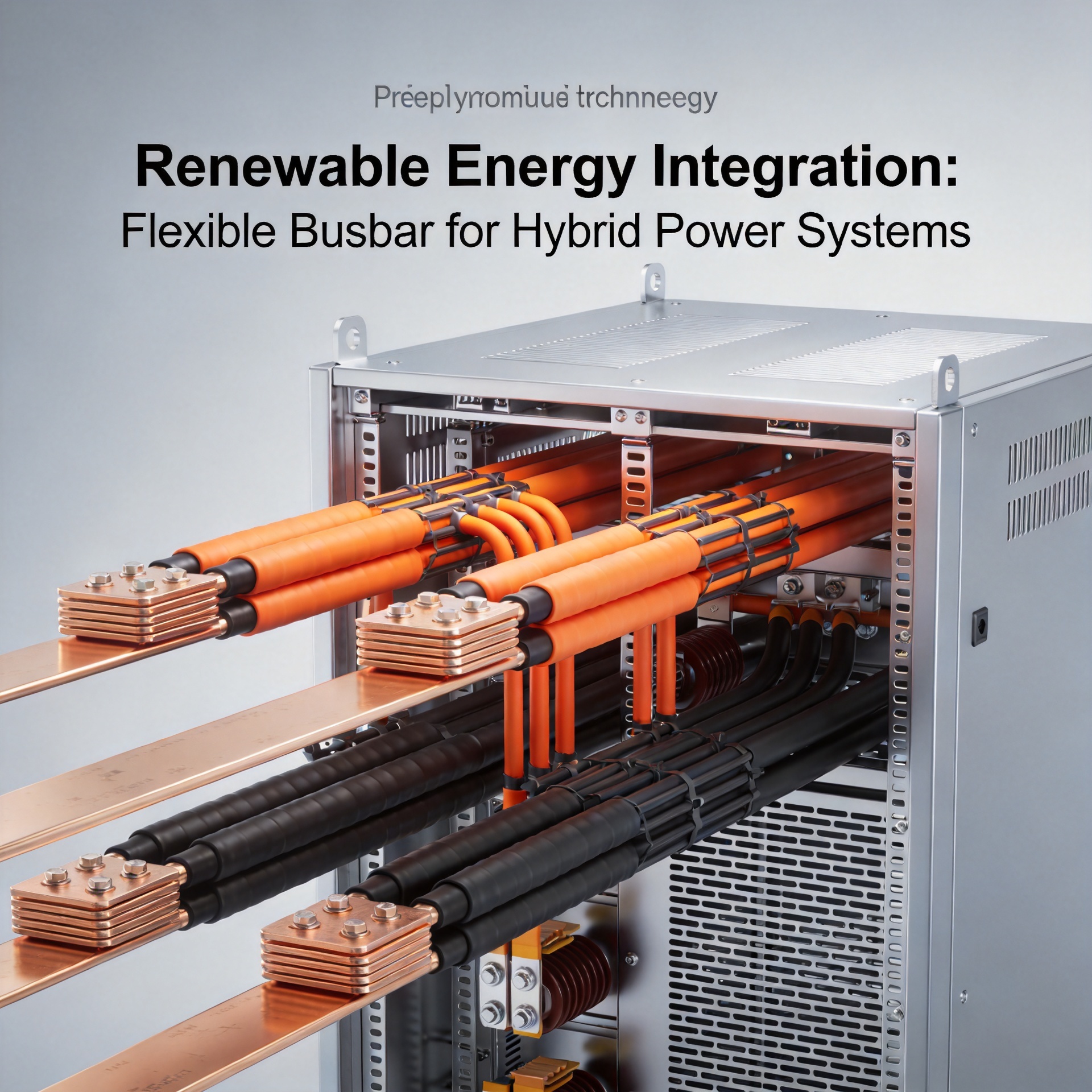
Quick answer: Flexible busbars are laminated copper or aluminum conductors that replace traditional cable harnesses in hybrid power systems, offering superior current distribution, reduced electromagnetic interference, and space savings of up to 60% in renewable energy applications [K1]. They serve as the primary power distribution backbone for solar inverters, wind turbine converters, and battery energy storage racks. While effective for medium-to-high current connections (50–600 A), they are not suitable for outdoor exposed installations without secondary enclosure. For procurement, specify required ampacity, operating voltage, bend radius, and insulation grade to ensure compatibility with your hybrid system design.
Application Scenario
Flexible busbars are increasingly specified in hybrid renewable energy systems where multiple power sources—solar arrays, wind turbines, battery banks, and grid connections—must be combined into a single, reliable power distribution network. Key installation environments include:
- Photovoltaic combiner boxes and inverters: Connecting multiple MPPT strings to a common DC bus
- Wind turbine nacelle and tower base: Routing power from generators to converters and transformers
- Battery energy storage systems (BESS): Interconnecting battery racks to inverters and system controllers
- Hybrid microgrid coupling points: Merging diverse energy sources onto a shared AC/DC bus
In these scenarios, flexible busbars provide low-impedance current paths that minimize voltage drop and heat generation—critical for maintaining system efficiency above 95% in high-throughput conditions.
Engineering Decision Criteria
When evaluating flexible busbars for hybrid power systems, prioritize the following criteria based on the source material [K1]:
| Criterion | Recommendation | Why It Matters |
|---|---|---|
| Current rating | 50–600 A per busbar layer | Matches typical renewable energy inverter and converter outputs |
| Voltage rating | Up to 1000 V DC / 690 V AC | Covers standard photovoltaic and BESS system voltages |
| Insulation class | Class B (130°C) or higher | Handles thermal stress from continuous high load |
| Bending radius | ≥ 6× busbar thickness | Prevents conductor fatigue and insulation cracking |
| Environmental seal | IP54 or better when enclosed | Protects against dust and moisture in utility cabinets |
| EMI performance | Laminated construction | Reduces radiated emissions and improves system noise immunity |
For engineering teams, the key trade-off is between flexibility and current-carrying capacity. A single 3-mm-thick layered busbar can carry up to 300 A, while adding parallel layers doubles capacity but increases stiffness.
Suitable vs. Not Suitable Cases
Suitable applications:
- Indoor cabinet wiring for power electronics
- Connections between battery modules and bus bars in racks
- Inverter-to-transformer low-voltage links
- Power distribution within prefabricated substations
- Retrofit installations where space constraints prevent cable bending
Not suitable applications:
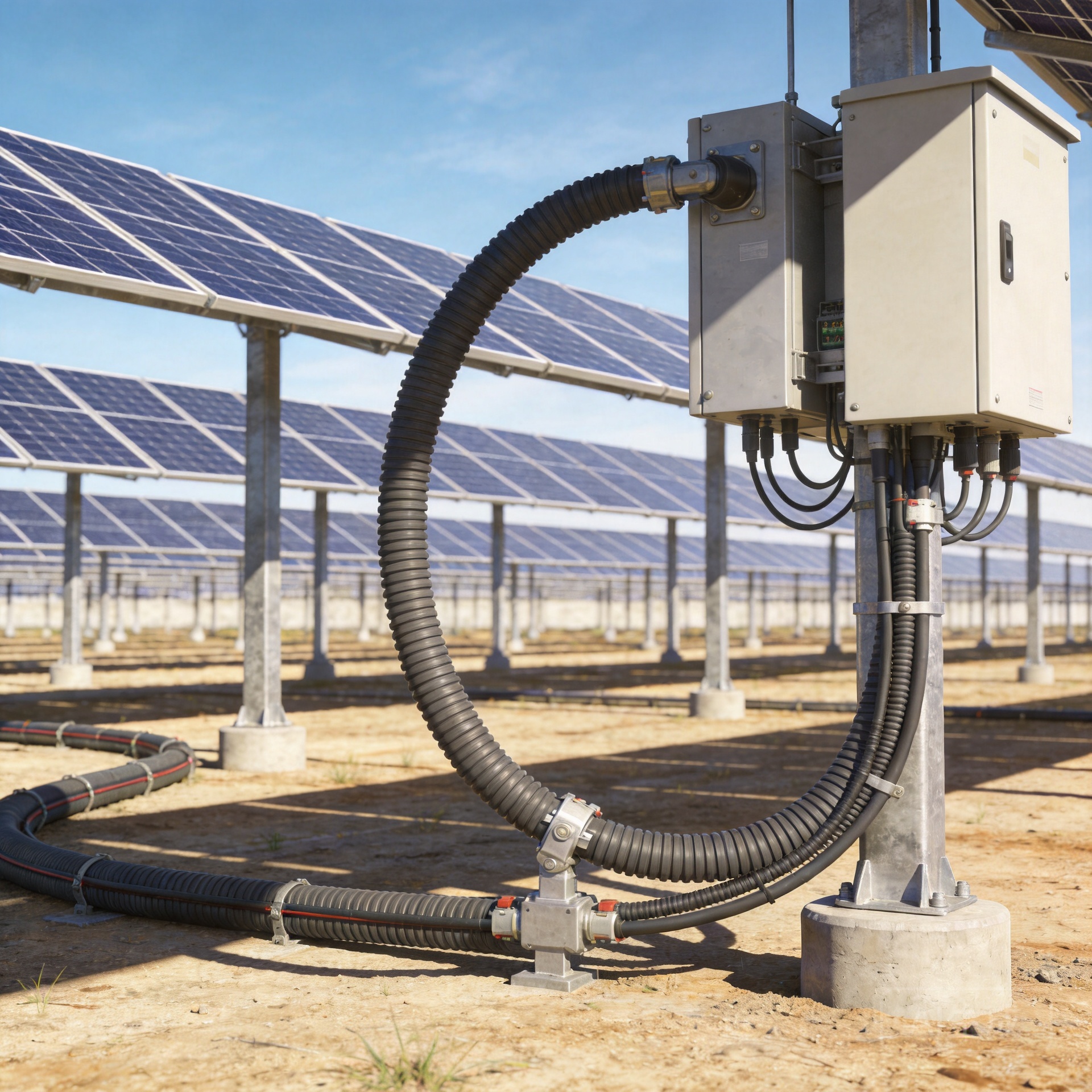
- Outdoor exposed runs without weatherproof conduit or enclosure
- Direct burial in soil or concrete (corrosion risk)
- High-vibration environments without additional support brackets
- Applications requiring frequent re-routing or re-termination (busbars are semi-permanent)
- Systems operating above 1000 V without specialized design review
Procurement Notes
When sourcing flexible busbars for hybrid power systems, provide the following to suppliers [K1]:
- Electrical specifications: Continuous current, peak fault current, rated voltage, and frequency (DC or AC)
- Mechanical constraints: Available mounting space, required bend radius, number of connection points
- Thermal requirements: Maximum ambient temperature and permissible temperature rise
- Environmental conditions: Indoor/outdoor, humidity range, chemical exposure
- Connection type: Bolt-on crimp lugs, compression terminals, or custom-shaped tabs
- Certification needs: UL 758, IEC 61439, or regional standards—confirm with manufacturer
Order lead time: Custom busbar assemblies typically require 2–4 weeks for design validation and production. Request a dimensional drawing approval before full production.
Frequently Asked Questions
Q: Can flexible busbars carry both AC and DC current in the same assembly?
A: Yes, but you must specify both ratings to the manufacturer. Laminated busbars with multiple layers can have separate AC and DC paths, provided the insulation between layers is rated for the combined voltage stress [K1].
Q: How does the cost of flexible busbars compare to traditional cable harnesses?
A: Flexible busbars typically have higher material cost per meter but can reduce total installed cost by 15–30% through faster assembly, reduced labor, and fewer support brackets. For high-density cabinets, the space savings often justify the premium.
Q: What is the typical lifespan of a flexible busbar in a renewable energy installation?
A: With proper specification and installation, flexible busbars can last 20–25 years. The limiting factor is usually the insulation material, not the conductor. Regular thermal imaging during maintenance can detect early signs of degradation.
Q: Do flexible busbars require special tools for installation?
A: Basic hand tools (torque wrench, crimping tool, multimeter) are sufficient. No soldering or welding is needed. Always follow the manufacturer’s torque specifications for bolt connections—typically 8–12 N·m for M8 bolts.
Q: Can I retrofit flexible busbars into an existing hybrid power system?
A: Yes, but you must verify the existing enclosure layout and connection geometry. Provide the manufacturer with a 3D model or detailed drawing of the installation area to ensure proper fit and clearance.
About the Author Yanghua Editorial Team — This article is maintained in the Astro MDX repository and reviewed against the source materials listed for the page.
Certifications, test reports, and performance claims require explicit approval before public publication.
Contact: info@yhflexiblebusbar.com | Phone: +86-769-3893-9888